Return to flip book view
Designation: F3561 − 22Standard Test Method forForced-Entry-Resistance of Fenestration Systems AfterSimulated Active Shooter Attack1This standard is issued under the fixed designation F3561; the number immediately following the designation indicates the year oforiginal adoption or, in the case of revision, the year of last revision. A number in parentheses indicates the year of last reapproval. Asuperscript epsilon (´) indicates an editorial change since the last revision or reapproval.1. Scope1.1 This test method sets forth the requirements and testingprocedures to test forced-entry-resistant building components,construction components, and specialty security equipment.This test method is intended primarily for manufacturers to testand rate their windows, doors, modular panels, glazings, andsimilar products to ensure that all manufactured products meetthe necessary requirements for forced-entry protection aftersustaining an active shooter assault.1.2 This test method is currently designed to simulate anactive shooter weakening the system with repetitive shotsfollowed by mechanically driven impact to simulate forcedentry.1.3 This test method is not to be used for ballistic resistantglazing rating. Test projectiles are permitted to perforate theentire specimen. The test projectile firings are intended tosimulate actions taken by an assailant to aid in the ability togain entry to a facility.1.4 This is a laboratory test to be performed on full systemsand therefore not applicable for field testing.1.5 All tests are executed on the exterior surface of thefenestration.1.6 Systems are required to be tested as complete units in atest frame or fielded conditions. Mulled systems must be testedin the mulled condition. Test results only apply to the compo-nent or system as tested. Once a system is tested and deemedto satisfy the requirements of this test method, no designchange can be made without a retest except those that qualifyunderAnnex A1 Substitution Criteria.1.7 Components (such as glazing, door leaves, etc.) may betested in accordance withAppendix X1, receiving a capabilitystatement for the component, but not a system rating per thisstandard.1.8 Window and door systems shall be rated to at least aminimum level of Test MethodsF476, F588,orF842,orcombinations thereof, as appropriate prior to commencing thistest evaluation. This test does not dual certify to the abovementioned standards.1.9 The values stated in this standard are SI units with theexception of the nominal descriptors for tools.1.10 This standard does not purport to address all of thesafety concerns, if any, associated with its use. It is theresponsibility of the user of this standard to establish appro-priate safety, health, and environmental practices and deter-mine the applicability of regulatory limitations prior to use.1.11 This international standard was developed in accor-dance with internationally recognized principles on standard-ization established in the Decision on Principles for theDevelopment of International Standards, Guides and Recom-mendations issued by the World Trade Organization TechnicalBarriers to Trade (TBT) Committee.2. Referenced Documents2.1 ASTM Standards:2A36/A36M Specification for Carbon Structural SteelA574 Specification for Alloy Steel Socket-Head Cap ScrewsC719 Test Method for Adhesion and Cohesion of Elasto-meric Joint Sealants Under Cyclic Movement (HockmanCycle)C1036 Specification for Flat GlassC1048 Specification for Heat-Strengthened and Fully Tem-pered Flat GlassC1135 Test Method for Determining Tensile Adhesion Prop-erties of Structural SealantsC1172 Specification for Laminated Architectural Flat GlassD1415 Test Method for Rubber Property—InternationalHardnessD3575 Test Methods for Flexible Cellular Materials Madefrom Olefin PolymersE631 Terminology of Building ConstructionsE3062/E3062M Specification for Indoor Ballistic TestRanges for Small Arms and Fragmentation Testing of1This test method is under the jurisdiction of ASTM Committee F12 on SecuritySystems and Equipment and is the direct responsibility of Subcommittee F12.10 onSystems Products and Services.Current edition approved Aug. 1, 2022. Published August 2022. DOI: 10.1520/F3561-22.2For referenced ASTM standards, visit the ASTM website, www.astm.org, orcontact ASTM Customer Service at service@astm.org. For Annual Book of ASTMStandards volume information, refer to the standard’s Document Summary page onthe ASTM website.Copyright © ASTM International, 100 Barr Harbor Drive, PO Box C700, West Conshohocken, PA 19428-2959. United StatesThis international standard was developed in accordance with internationally recognized principles on standardization established in the Decision on Principles for theDevelopment of International Standards, Guides and Recommendations issued by the World Trade Organization Technical Barriers to Trade (TBT) Committee.1'RZQORDGHG3ULQWHG$FFHVVHGE\XVHU(UQHVWR1LFRODV_'DWH7KX6HS
Ballistic-resistant ItemsF476 Test Methods for Security of Swinging Door Assem-bliesF588 Test Methods for Measuring the Forced Entry Resis-tance of Window Assemblies, Excluding Glazing ImpactF842 Test Methods for Measuring the Forced Entry Resis-tance of Sliding Door Assemblies, Excluding GlazingImpactF1915 Test Methods for Glazing for Detention Facilities2.2 Other Standards:ISO/IEC 17025:2005 General Requirements for the Compe-tence of Testing and Calibration Laboratories33. Terminology3.1 Definitions of Terms Specific to This Standard:3.1.1 component, n—integral part of a forced entry testspecimen such as: panels, frame, glazing, glazing bite, flanges,hinges, locks, jamb/wall, jamb/strike mullions, and mountingdevices of different shape, size, and material.3.1.2 door, double, n—two-door assembly with an openingwider than as a single door with a common latch and lock edge;may or may not include a removable mullion; openings may beasymmetrical with regard to the size of openings.3.1.3 door panel, n—the swinging or sliding barrier bywhich an entry is closed and opened, not including framing,operating, or latching mechanisms.3.1.4 failure criteria, n—any failure of the manufacturer’srecommended mounting hardware or penetration of any por-tion of the system sufficient to permit passage of the test shape.3.1.5 fenestration, n—any glazed panel, window, door, cur-tain wall, or skylight unit on the exterior of a building.3.1.6 glazing weakening, v—intentional structural deteriora-tion of a glazing or glazing infill.3.1.7 impact assault, n—test of forced entry attack using animpactor on one dissimilar component in an attempt to createan opening and permit passage of the test shape.3.1.8 impactor, n—45 kg striking mechanism capable ofbeing deployed in a pendulum motion.3.1.9 independent test facility, n—testing laboratory accred-ited to perform the referenced testing procedures by a nation-ally recognized accrediting agency in accordance with ISO/IEC 17025.3.1.10 mulled, n—the physical connection together of twoparts of the same system; the two systems may be anchoreddirectly to each other or have a mullion between them.3.1.11 mullion, n—a component used to divide two parts ofthe same system and it can be vertical or horizontal, movableor fixed; for purposes of this test method, a mullion does notinclude steel or concrete structural members (including seismicjoints) which are present in the building.3.1.12 ready-to-install, n—fabricated, with an appropriatefinal finish such as galvanizing, paint, or anodizing; the testspecimen shall consist of the entire fenestration assembly andcontain all devices used to resist forced entry; all parts of thetest specimen shall be full size, as specified for actual use,using the identical materials, details, and methods of construc-tion.3.1.13 shop assembly drawing, n—a drawing which showshow a system is assembled including the locations, dimensions,and arrangements of all assembly elements such as bolts,glazing stops, and glazing spacers.3.1.14 system, n—the assembly of structural elements anddevices which comprise the forced-entry-resistant barrier.3.1.15 test director, n—the individual identified by theindependent testing laboratory as being responsible to com-plete the specified tests as required and to document the results,in accordance with this test method.3.1.16 test facility, n—laboratory or other area whereforced-entry testing is conducted.3.1.17 test fixture, n—the structural assembly which holdsthe test specimen.3.1.18 test levels, n—the increments to which systems aretested.3.1.19 test plane, n—a plane parallel and contiguous to theface of the attack side of the test sample.3.1.20 test projectiles, n—projectiles or ammunition that isused to weaken the test specimen.3.1.21 test shape, n—a non-compressible sphere measuring152 mm (6 in.) in diameter.3.1.22 test tools, n—the devices used by the test team duringthe assault tests.3.1.23 testing report, n—a report provided by the testfacility that includes configuration documentation, any appli-cable abnormality, forced-entry testing data and photographs, acertification of testing, a narrative summary of testing, time-stamped drawings that have been validated to match the testspecimen, and all video recording(s) of testing.3.1.24 view window, n—a window system which permitsvisual contact through an otherwise opaque host assembly.3.1.25 window frame, n—the opaque portion of a transpar-ent assembly into which the transparent element is mounted.3.1.26 yaw, n—the angular deviation between the test pro-jectile’s axis of symmetry and its line of travel.3.2 Abbreviations:3.2.1 AN—annealed3.2.2 C1—center 13.2.3 C2—center 23.2.4 CS—chemically strengthened3.2.5 E—East3.2.6 FMJ—Full Metal Jacket bullet3.2.7 FT—fully tempered3.2.8 ft/s—feet per second3.2.9 ft·lbf—foot pound-force3.2.10 H—drop height3Available from International Organization for Standardization (ISO), ISOCentral Secretariat, Chemin de Blandonnet 8, CP 401, 1214 Vernier, Geneva,Switzerland, https://www.iso.org.F3561 − 222'RZQORDGHG3ULQWHG$FFHVVHGE\XVHU(UQHVWR1LFRODV_'DWH7KX6HS
3.2.11 HS—heat-strengthened3.2.12 in.—inch(es)3.2.13 IRHD—international rubber hardness degree3.2.14 J—joules3.2.15 kg—kilogram3.2.16 L—horizontal swing distance3.2.17 lb—pound3.2.18 m/s—meters per second3.2.19 mm—millimeter3.2.20 MSG—manufacturers standard grade3.2.21 n—noun3.2.22 N—North3.2.23 N—Newtons3.2.24 NE—North East3.2.25 NW—North West3.2.26 oz—ounce3.2.27 R—radius of swing3.2.28 S—South3.2.29 SE—South East3.2.30 SW—South West3.2.31 v—verb3.2.32 W—West4. Summary of Test Method4.1 This test method establishes incremented levels offorced-entry protection via evaluation of a two-stage attack ofa single or mulled system by using a device for weakening ofcomponents prior to forced entry impact of the fenestrationsystem.5. Significance and Use5.1 The test requirements specified herein have been estab-lished for use in evaluating the forced-entry resistance charac-teristics of assemblies to be used in commercial, residential,schools, government, and other institutional installations wherethe risk of a single person active shooter attack is present.5.2 The procedures of this test method are intended toevaluate the ability to create an opening of sufficient size topermit passage of a test shape through it.5.3 The procedure presented herein is based on post-eventexamination and are not intended to be used to establish orconfirm the absolute prevention of forced entries.6. Apparatus6.1 Apparatus to conduct these tests include ballistic firingmechanism or means to simulate ballistic type weakening, testfixture, impactor, measurement device, test shape, and forcemeter.6.2 Test Fixture—The test fixture shall be sized to accom-modate the test specimen and in accordance with design ofFigure 1 in Test MethodsF1915, or as specified by theauthority having jurisdiction provided it does not enhance ordegrade the specimen.6.3 Velocity Measurement System—The velocity measure-ment system shall be capable of providing projectile velocitieswith at leasta1×10–6sec sampling resolution and an accuracyof at least 61.5 m/s (65 ft/s).6.4 Support Fixture and Frame—The test specimen shall bemounted in the frame along the full length of all edges or asspecified by the manufacturer’s installation instructions.6.4.1 The frame shall have a clamping plate to hold the testspecimen in position and means for producing uniform clamp-ing of the specimen.6.4.2 All edges of the test specimen shall be uniformlyclamped with a clamping pressure sufficiently large that theedges remain in position during the test. The test specimen inthe frame shall be placed normal to the direction of attack withan accuracy of 60.02 rad (1°(degree)) in any orientation. Testspecimen shall be oriented to strike face in accordance withmanufacturer’s documentation. Manufacturer shall clearlymark the strike face on each specimen. The support andretention system shall be reported.6.4.3 The test fixture shall simulate installation in a perma-nent steel or concrete structure which neither enhances nordegrades the forced-entry protection of the system.6.5 Glass Weakening Device—The glass weakening deviceshall be capable of firing 10 test projectiles meeting therequirements ofTable 1.6.5.1 Test projectiles shall be fired using:6.5.1.1 AR-15 5.56 Rifle, capable of discharging projectilesin accordance with6.5.6.5.1.2 Ballistic Firing Mechanism, capable of dischargingprojectiles in accordance with6.5.6.6 Forced Entry Impactor System:6.6.1 Impactor:6.6.1.1 The forced entry impactor shall be a pendulumsystem with a cylindrical weight capable of delivering hori-zontal impacts of 542 J (400 ft·lbf).6.6.1.2 The diagram of the impactor is shown inFig. 1.Itisa steel cylinder 152 mm 6 6mm(6in.6 0.25 in.) in diameter,TABLE 1 Test ProjectilesAmmunition Description Ammunition IdentityClassification (AIC)Bullet Weight(grain)Velocity (Meters (ft/s))±10 m/s (±33 ft/s)5.56 NATO,Copper Jacket Lead Core, FMJM193 55 1027 m/s (3370 ft/s)F3561 − 223'RZQORDGHG3ULQWHG$FFHVVHGE\XVHU(UQHVWR1LFRODV_'DWH7KX6HS
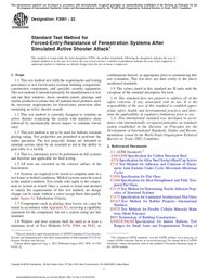
360 mm 6 45 mm (14 in. 6 1.75 in.) long, with a hemispheri-cal impact nose 152 mm 6 6mm(6in.6 0.25 in. ) in diameterand maximum 76 mm (3 in.) deep. The impactor including eyebolts weighs 45 kg 6 1 kg (100 lb 6 2 lb).6.6.1.3 The shot is used to obtain the proper weight of theimpactor as needed. The shot should be constrained in holdersattached to the impactor to avoid excessive movement duringtesting. The shot is to be positioned evenly to balance theweight of the impactor front to back in the suspension system.6.6.1.4 The impact nose used in this equipment is madefrom cast epoxy polyamide resin; however, any durableimpact-resistant material is satisfactory.6.6.1.5 The durometer of the impact nose shall be Shore Dhardness 80 6 10.FIG. 1 Impactor DetailsFIG. 2 Impactor Swing and Measurement SchematicF3561 − 224'RZQORDGHG3ULQWHG$FFHVVHGE\XVHU(UQHVWR1LFRODV_'DWH7KX6HS
6.7 Suspension System:6.7.1 The suspension system for the impactor consists offour flexible steel cables providing a swing radius of 1710 mm6 52 mm (67 in. 6 2 in.), as shown inFig. 2.NOTE 1—Fig. 2 is for example only. Suspension system should becapable of allowing adequate, smooth, and consistent delivery of desig-nated force.6.7.2 Fig. 3 includes a diagram of the pendulum systemwhen elevated and at rest, and the measurements required tocalculate the impact energy of the system.6.7.3 These cables are adjusted to equal length with turn-buckles such that the impactor swings in a straight, true arc andare attached to a steel frame that can be adjusted to be level(Fig. 2).6.7.4Table 2 presents the potential energy of a pendulumsystem with a 45 kg 6 1 kg (100 lb 6 2 lb) weight as afunction of various elevations of the weight. The suspensioncables are not included in the weight and energy calculations ofthe impactor.6.8 Test Shape—The test shape used to determine if passagehas been achieved is defined in3.1.21.7. Hazards7.1 This test method involves potentially hazardous situa-tions. Proper precautions shall be taken by the test facility toprotect workers, observers, and the community. The testlocation shall be secured to prevent unauthorized access duringtesting. All testing personnel and observers shall be kept out ofthe path of the projectile and behind a hardened barrier tominimize ricochet or fragmentation hazards during testing. Themain backstop shall be designed to safely contain the projectileand prevent damage to life or property down range in theprojectile’s line of flight.7.2 The testing lab shall be properly designed to minimizehealth effects to workers resulting from lead dust exposure.Proper handling, storage, and disposal of lead contaminatedmaterials shall be consistent with all local and federal laws andrequirements found in the Resource Conservation & RecoveryAct of 1976.8. Test Specimens8.1 Systems submitted for testing shall be full-size systemscomplete with all required anchor bolt system hardware andrepresentative of production systems.8.2 Systems that move or operate (for example, doors,hatches, operable windows) shall, at minimum, include alldevices required for operation.8.3 The test specimen shall be ready-to-install.8.4 Three (3) test specimens of identical construction shallconstitute a sample set for testing.FIG. 3 Detail of Impactor Cable SystemTABLE 2 Potential Energy of Impactor and Drop HeightLevelPotential Energy, J Height of Drop (H)J (ft*lbf) mm (ft)1 68 50 152 0.502 136 100 305 1.003 203 150 457 1.504 271 200 610 2.005 339 250 762 2.506 407 300 914 3.007 475 350 1067 3.508 542 400 1219 4.00F3561 − 225'RZQORDGHG3ULQWHG$FFHVVHGE\XVHU(UQHVWR1LFRODV_'DWH7KX6HS
9. Preparation of Apparatus9.1 Preparation:9.1.1 Review the test specimen configuration and testsample documents supplied in accordance with9.1.2 to ensurethe proper sample is being tested.9.1.2 Ensure testing apparatus is in good condition andconfigured per6.2.9.1.3 Install test specimen in support fixture per6.4.9.1.4 Support Fixture and Frame—The test specimen shallbe mounted in the frame along the full length of all edges.9.1.4.1 The frame shall have a clamping plate to hold thetest specimen in position and means for producing uniformclamping of the test specimen.9.1.4.2 All edges of the test specimen shall be uniformlyclamped with a clamping pressure sufficiently large that theedges remain in position during the test.9.1.5 Forced-entry test specimens shall be mounted inaccordance with all the requirements of this section.9.1.5.1 The mounting of the test specimen must give noleverage advantages and shall not influence the performance ofthe test specimen over the expected mounting conditions in thefield.9.1.5.2 The test specimen shall be mounted in accordancewith the manufacturer’s instructions with particular attentionpaid to the threat and protected side orientation during mount-ing.(1) If the test specimen cannot be mounted according to theinstallation instructions submitted by manufacturer, the testshall not be conducted.9.1.5.3 If the tested product type is typically installed in anopening larger than the tested product size (for example, in a“rough opening”), the test specimen shall be mounted in arough opening of 8 mm 6 2 mm (0.315 in. 6 0.08 in.) largeron all sides than the test specimen.9.1.5.4 For specimens that require footers, the test speci-mens shall be erected (including those cast in place) onfootings, and either back-braced or capped with a simulatedroof or ceiling panel to ensure that the bracing or cappingreflect standard fielded conditions.10. Specimen Preparation and Mounting10.1 Glazing System Tests—The test specimen will bemounted in accordance with the manufacturer’s recommenda-tions and shall be securely anchored. Consideration should begiven to, but is not limited to:10.1.1 Overall size of glazing system;10.1.2 Amount of “bite” within the frame;10.1.3 Integrity of the frame;10.1.4 Strength of base material;10.1.5 Size of removable stop;10.1.6 Removable stop fastener;10.1.7 Interface between glazing and frame; and10.1.8 Integrity of anchorage of glazing system to adjoiningarchitectural features.NOTE 2—The clamping pressure has relatively little effect on the testresults for glass but can have considerable influence on the test results forplastic glazing sheet materials. For these materials, the manner of supportand retention shall be reported.10.2 The specimen shall have an edge support/coverage onall edges of 38 mm 6 6 mm (1.5 in. 6 0.25 in.). The specimenshall be separated from the frame and the clamping plate bycontinuous rubber strips, 5 mm 6 0.5 mm (0.197 in. 60.02 in.) thick, 30 mm 6 5 mm (1.18 in. 6 0.197 in.) wide andof hardness (50 6 10) IRHD, in accordance with Test MethodD1415.NOTE 3—The rigidly supported fixture prevents specimen translationalong the line of flight but permits its position and attitude to be readilyadjusted so that it is perpendicular to the line of flight at the projectilepoint of impact.10.2.1 The test specimen in the frame shall be placednormal to the direction of attack with an accuracy of 60.02 ra-dians (61° (degree)) in any orientation. Test specimen shall beoriented to strike face in accordance with manufacturer’sdocumentation. Manufacturer shall clearly mark the strike faceon each specimen. The support and retention system shall bereported.11. Calibration and Standardization11.1 Apparatus shall be inspected for defects prior totesting, be in good working condition and not defective.11.2 Velocity of the ballistic firing mechanism shall beverified.11.2.1 Velocity Measurement System—The velocity mea-surement system shall be capable of providing projectilevelocities with at leasta1×10–6sec sampling resolution andan accuracy of at least 61.5 m/s (65 ft/s). The system shallmaintain position and alignment throughout the testing se-quence and shall minimize the effects of shock waves, soundwaves, ultraviolent and infrared light, ejected propellant,sabots, and other debris that can decrease measurement accu-racy. Redundant velocity measurement system is required.11.2.2 If radar, high-speed video, or X-ray is used forvelocity measurement, the velocity reported shall be thevelocity measured at 2.3 m 6 2.5 cm (90 in. 6 1.0 in.). fromthe plane of the test item.11.2.3 If light screens are used for velocity measurement,the requirements below shall be met.11.2.3.1 The light screens shall be positioned as shown inSpecificationE3062/E3062M.11.2.3.2 The inner screens shall be paired together, and theouter screens shall be paired together.11.2.3.3 The light screen pairs shall be parallel to each otherand perpendicular to the projectile firing system barrel.11.2.3.4 The distance from the last light screen to the testitem reference plane shall be no greater than 1.5 m (5 ft).11.2.3.5 The light screens shall be fastened together toprevent inadvertent changes in spacing.NOTE 4—The spacing between the light screens may be adjusted tomeet velocity measurement requirements.11.3 Impactor weight shall be verified to be 45 kg 6 1kg(100 lb 6 2 lb).11.4 Impactor nose cone shape and dimensions shall beverified through measurement, free of gouges or cuts deeperthan 12 mm (0.5 in.), and durometer shall be an average of 806 10 Shore D when measured in three distinct locations on theF3561 − 226'RZQORDGHG3ULQWHG$FFHVVHGE\XVHU(UQHVWR1LFRODV_'DWH7KX6HS
nose cone, with a minimum of one location being at the centerof the impacting face of the nose cone.12. Conditioning12.1 Specimens shall be conditioned prior to testing toensure all components have reached temperature equilibrium.12.2 Testing shall be performed at an ambient temperatureof 22 °C 6 4 °C (72 °F 6 7 °F).13. Test Director Role13.1 The Test Director is responsible for safety and willensure that all reasonable safety precautions are employed.13.2 Safety—The test may be interrupted for reasons ofsafety (imminent danger to or injury of test personnel). Thisinterruption in the test will not be used for clearing awaydebris, such as glass fragments produced during testing, fromthe test specimen. Any modifications to the test specimen madefor safety reasons must be agreed to by all parties and must notin any way enhance or detract from the sample’s forced-entryresistance.13.3 The Test Director’s goal is to ensure consistency in theapplication and performance of this test. The Test Directorshall direct impacts and verify the system to the pass/failcriteria presented in this document. The Test Director shall beprovided a full set of plans prior to the test.13.4 The Test Director shall, at a minimum, ensure thefollowing:13.4.1 Only those resources (impactor) specified may beapplied to the test specimen once forced-entry testing hascommenced;13.4.2 Impactor and firing device are used safely andappropriately; and13.4.3 The elapsed time between the weakening of theglazing and impact commencing shall be minimized and shallin no case exceed 2 h in order to simulate actual durations ofattack as closely as possible in a controlled environment.14. Procedure for Panel Operability14.1 Prior to any testing of the system, the system shall haveits operability measured and recorded. No assembly shall bemodified or enhanced once operability has been recorded.14.2 Additional attachments that increase the strength of theconnection between the operable locking devices and thesystem are not permitted. Operation of the locking devicesshall be done in a manner that will not cause collateral damageto the specimen.14.3 Panel Operability Test:14.3.1 This test applies only to systems that may be opened.14.3.2 Close and lock all portions of the test specimen.Submit each operable unit to five cycles of opening, closing,and locking prior to testing.14.3.3 After panel operation test sequence, the test speci-men shall be considered operable per the manufacturer’swritten installation instructions.14.3.4 Fenestration shall be locked prior to initiating anytest projectile firings and the locks not operated again until thecompletion of the forced entry impactor tests.14.3.5 At the completion of the final forced entry impact testsequence, the operability of the system shall be verified inaccordance with Section14; however failure to operate is nota condition of passing this test. The ability to operate the locksand open the system shall be noted in the report.15. Procedure for Fenestration Weakening15.1 Glazing or Panel Weakening:15.1.1 Glazing or panel shall be pre-weakened by testprojectiles prior to impact testing.15.1.2 Test pattern shall be centered on the target compo-nent (normally geometric center of the glazing or panel) witha minimum distance from the inner edge of the frame being52 mm (2 in.).15.1.3 Test pattern diameter shall be 457 mm 6 6mm(18 in. 6 0.25 in.) with all the impacts being positioned withinthe tolerance of the diameter with 0.785 radian 6 0.05 radian(45° 6 3°) separation between shots. The center shots (C1 andC2) shall be located 52 mm 6 6mm(2in.6 0.25 in.) from thegeometrical center and along the W to E axis with 104 mm6 6mm(4in.6 0.25 in.) distance between the center of eachshot.15.1.4 Test Projectile Firing—Ammunition of the appropri-ate type and caliber (see6.5) shall be single-fired to obtain therequired number of fair hits on each test specimen. Shots shallutilize the shot pattern shown inFig. 4.15.1.5 The sequence of projective firing shall be N, S, W, E,followed by NW, SW, NE, SE, C1 and C2 as indicated inFig.4.15.1.6 The orientation and sequence of the shots shall not bechanged.15.2 Procedure for Lock Weakening:15.2.1 Lock mechanisms in doors shall be pre-weakened bytest projectiles prior to impact testing.15.2.2 Test pattern shall be offset (to the right or left) of thelocking mechanism so that the applicable West or East mostfiring impacts the center of the lock with the remaining shotson the door panel (Fig. 7).15.2.3 Test pattern diameter shall be 229 mm 6 6mm(9in.6 0.25 in.) with all the impacts being positioned within thetolerance of the diameter with 1.571 radian 6 0.05 radian (90°6 3°) separation between shots. The center shot (C3) shall belocated to the side (right or left) and perpendicular to thevertical center of the locking mechanism (typically a panelimpact location).15.2.4 Test Projectile Firing—Ammunition of the appropri-ate type and caliber shall be single-fired to obtain the requirednumber of fair hits on each test specimen. Shots shall utilizethe shot pattern shown inFig. 5.15.2.5 The sequence of projective firing shall be C3, fol-lowed by N, S, E, W as indicated inFig. 5. The final shot shallbe on the lock mechanism.15.2.6 The orientation and sequence of the shots shall not bechanged.15.3 Fair and Unfair Hits—For purposes of this testmethod, a fair hit shall be a zero-degree obliquity ballisticimpact (63°) using the specified weight and type of un-yawedF3561 − 227'RZQORDGHG3ULQWHG$FFHVVHGE\XVHU(UQHVWR1LFRODV_'DWH7KX6HS
bullet (0.05 radian (3°) maximum)) within the specified veloc-ity range on the specified location of the test sample. Yaw ismeasured at the point of impact but no further than 300 mm(12 in.) from the front surface of the specimen. All other firingsshall be classified as unfair, and require retesting, except:15.3.1 An impact at more than the maximum acceptablevelocity which does not cause panel perforation, but which isotherwise a fair hit, shall be classified as a fair hit at thediscretion of the manufacturer.15.3.2 In the case of an unfair hit, at the discretion of themanufacturer, select one of the following to continue testing:15.3.2.1 Restart the pattern on a new sample; or15.3.2.2 Fire a replacement shot that is closer to the in-tended pattern than the unfair hit.FIG. 4 Test Projectile Firing Pattern for Glazing and PanelsFIG. 5 Test Projectile Firing Pattern for Door Locking MechanismF3561 − 228'RZQORDGHG3ULQWHG$FFHVVHGE\XVHU(UQHVWR1LFRODV_'DWH7KX6HS
15.3.2.3 Restarting the pattern is limited to only one speci-men per sample set.15.4 Evaluate glazing for passage of test shape at any timeduring the test projectile firing pattern when the Test Directorbelieves passage for failure is possible.15.4.1 No additional damage may be done to the glazingsystem, including hand manipulation of fragments when evalu-ating test shape passage.16. Procedure for Forced-Entry Testing16.1 Forced-entry testing, regardless of the type of assem-bly being tested, shall consist of glazing weakening followedby mechanical forced-entry impacts.16.2 The impact assault will be at the center of the glazingor panel.16.3 The impact assault for the lock shall be centered on testprojectile shot C3 ofFig. 5.16.4 Designate Forced-Entry Test Force Level:16.4.1 Target force shall be selected fromTable 2.16.5 Perform the impact assault testing for the selectedresistance force on each dissimilar component.16.5.1 With the impactor at rest, the furthest protrudingpoint of the impacting nose cone shall be located no more than52 mm (2 in.) from the surface of the specimen and no morethan 52 mm (2 in.) in any direction from the intended impactlocation on the specimen.16.5.2 Align the impactor with the impact position asrequired. Raise the impactor to the selected drop heightintended for classification and stabilize it. At the selected dropheight, the suspension device shall be taut, and the axes of theimpactor and cable shall be in line.16.5.3 The impactor, stabilized in the launch position in avertical plane normal to the test specimen, is released and fallswithout initial velocity or axial rotation.16.5.4 Inspect each test specimen after each impact andrecord and report whether it complied or did not comply withthe applicable interpretation of results.16.5.5 Impacts start at the lowest drop height fromTable 1and advance through each level by successively increasing thedrop height until the target level or failure is reached.16.5.5.1 The test specimen must pass two (2) sequentialimpacts from the same drop height for it to be deemed a passat that level, or to move on to a higher level.16.5.6 Specimens may be reused for higher classificationimpact testing.16.5.7 For systems with bent glass, each specimen of bentglass will be impacted on the convex surface at the center ofthe specimen perpendicular to the frame from the selected dropheight.NOTE 5—The convex surface is tested due to the realistic constraints ofthe test set-up in impacting the concave surface. Additionally, as of thedate of this publication no data was available that showed one surface ismore or less likely to break during impact.16.5.8 Conduct forced-entry testing at each component untilone of the following conditions is met:16.5.8.1 The system fails due to any of the criteria inSection18;or16.5.8.2 The selected forced-entry resistance level is metwithout failure.(1) The force level is considered a pass when all locationsdesignated for impact on a system in accordance with Section17 are passed successfully at the same force level.16.5.9 If any of the required specimens fail to comply withthe requirements of Section18, the material shall not beclassified for forced-entry impact.16.6 No repairs or replacement of damaged components arepermissible during or between any glazing weakening orforced-entry tests.17. Attack Types17.1 A test specimen shall be tested at all dissimilar com-ponents via a separate concentrated assault. Every dissimilarportion (section) is tested for at least as long as the intendedrating of the system as a whole. To achieve the intended systemrating, every dissimilar component must deny forced entry forthat test sequence.17.2 Door Attack Type:17.2.1 Perform individual testing on three separate testspecimens. Each assault should be the same force as thedesired forced entry resistance level. Use two door systems forglazing weakening and impact, and one door system for lockweakening and impact. Perform forced-entry impact assault onthe door panel or glazed areas (Fig. 6), and one lock weakeningand forced entry impact on the latch/lock area (Fig. 7) only.The test projectiles shall be fired to impact the door and offset(to the right or left) from the lock so that the applicable Westor East most projectile impacts the center of the lock (seeFig.7). The attack direction shall be from exterior to interiorindependent door seating.17.2.1.1 The door will qualify at the lowest level of forcedentry determined from either the glazing or lock assault testing.17.2.1.2 At the request of the manufacturer, the forced entryassault of the glazing and the lock weakening forced entryassault may be performed on each sample, however the intentis to use three specimens, two for the glazing assault and onefor the lock assault.17.2.1.3 For double door systems, the assault is only per-formed on the main locking system and not the point locklocations.17.2.2 A double-door must be tested in its double-doorconfiguration. Additional impact attacks should be conductedat the mid-span of the center whether a mullion is present ornot (Fig. 8). If doors contain glazing, they must additionally beimpacted per the window attack type that follows. Symmetricalconstruction features do not need to be tested more than once.17.3 Window Attack Type:17.3.1 Perform a minimum of two separate forced-entryimpact assaults on a window at the same impact level. Impactdrop height starts at the lowest level and progresses to higherdrop heights after two successful impacts at the same height.Perform the assault at the center of the glazing (Fig. 9).17.4 Panel Attack Type:17.4.1 Perform a minimum of three separate forced-entryimpacts on a panel. Perform at least one impact at the center ofF3561 − 229'RZQORDGHG3ULQWHG$FFHVVHGE\XVHU(UQHVWR1LFRODV_'DWH7KX6HS
the panel (Fig. 10), at least one impact at the corner of the panel(Fig. 10), and one impact at the panel frame pocket (Fig. 10).FIG. 6 Descriptors for Single Door Attack SequenceNOTE 1—West most impact indicated by arrow.FIG. 7 Descriptors for Single Door Test Projectile ImpactsF3561 − 2210'RZQORDGHG3ULQWHG$FFHVVHGE\XVHU(UQHVWR1LFRODV_'DWH7KX6HS
18. Forced-Entry Pass Criteria18.1 The goal of the testing is to determine system capabil-ity in preventing the development of an opening in the testplane that allows passage of the test shape after weakening orimpact. The testing is considered a pass if all the followingcriteria are met:18.1.1 The test shape cannot be passed entirely behind aplane parallel and contiguous to the face of the attack side ofthe test specimen by a single attack team member, using onlytheir hands to guide the test shape and a force meter. No greaterthan 18 N (4 lb) force shall be exerted on the test shape at anytime during or at the end of glazing weakening testing or forcedentry impact testing to pass it through an opening.18.1.1.1 Operable systems that open upon glazing weaken-ing or impact testing and allow passage of the test shape are notconsidered a pass.19. Interpretation of Results19.1 After all of the test sequences have been completed, thesystem will be assigned a “Fail” rating or a “Pass” rating withan associated forced-entry rating level.19.2 System is assigned a Fail rating if it does not meet allof the criteria in Section18.19.3 System is assigned a Pass rating with a system forced-entry rating that is equal to the lowest “pass” force of all of theindividual test specimens.FIG. 8 Descriptors for Double Door Attack SequenceFIG. 9 Descriptors for Window Attack SequenceF3561 − 2211'RZQORDGHG3ULQWHG$FFHVVHGE\XVHU(UQHVWR1LFRODV_'DWH7KX6HS
19.4 Substitution Criteria—See Annex A1.20. Report20.1 General Test Data Reporting Procedure:20.1.1 Once a system is tested according to this test method,a final report of all testing results shall be submitted to therequisitioner regardless of testing outcome. All test reports aswell as any information concerning the results of each test areconsidered proprietary and shall not be discussed or releasedwithout prior approval of the requisitioner and the manufac-turer.20.1.2 Test Report Requirements:20.1.2.1 The testing laboratory will provide the requisi-tioner with a testing report that shall be an all-inclusivedocument with the data and results of all testing, as well as allother documentation required by this section. This includes theconfiguration documentation, any applicable abnormalities,panel operability results, glazing weakening details and results,forced-entry data, testing photographs, the certification oftesting, the narrative summary of testing, and all video record-ing(s) of testing.20.1.2.2 Report Title and General—The title of the reportshall contain:(1) Indicate the type of report, that is “Test Report;”(2) The system model number, level of forced-entry re-sisted as defined by forced-entry resistance testing levels;(3) Date, time, and location of testing; and(4) Temperature of laboratory during testing, specimensurface temperature.20.1.2.3 Configuration Documentation:(1) The report shall contain complete configuration docu-mentation including drawings that have been validated tomatch the test specimen and a list of materials not otherwisedescribed by the drawings. Comments concerning inconsisten-cies between the assembly and its documentation shall beexpressed in the testing report.20.1.2.4 Panel Operability Data:(1) Include detailed results and discussion of the paneloperability test (where applicable).20.1.2.5 Glazing Weakening Data:(1) Include detailed results and discussion of the glazingweakening performance including any deviation from thepattern, abnormal breakage, and any openings that developed.20.1.2.6 Forced-Entry Test Data:(1) Include detailed data records of forced-entry testingincluding impactor details, drop height, calculated or measuredforce, and if applicable, penetration details with opening sizemeasurements before test shape evaluation, then test shapepenetration results and the overall results of forced-entrytesting.20.1.2.7 Photographic Record of Testing:(1) Submitted as 5 megapixel resolution (minimum) digitalphotographs of the test specimen:(2) Before testing;(3) After all glazing weakening shots have been completed;(4) After each level of forced-entry impact; and(5) If applicable, the point at which entry is forced.(6) Each photo should specify: (1) model number (2) adescription of the view, (3) the test phase description, (4)glazing configuration (if applicable to photo), and (5) themanufacturer.20.1.2.8 Narrative Summary of Testing:(1) A narrative summary shall be provided which includes:(2) The identity of the test facility,(3) A description of the sample,(4) A description of the testing,(5) A description of the results, and(6) A detailed explanation of any conditions (for example,test temperature, glazing size) that do not meet the require-ments of this test method.20.1.2.9 Video Recording of Testing:FIG. 10 Descriptors for Panel Attack SequenceF3561 − 2212'RZQORDGHG3ULQWHG$FFHVVHGE\XVHU(UQHVWR1LFRODV_'DWH7KX6HS
(1) All forced-entry testing shall be recorded in its entirety.Video recording(s) shall be provided to the requester in theform of physical or electronic media. The recording(s) shallinclude appropriate audio narrative description and comments.Acceptable file formats for these videos are: Audio VideoInterleave (.avi file extension), Windows Media Format (.wmvfile extension), and Moving Pictures Expert Group (.mpg or.mpeg file extensions). Include the date, location, and descrip-tion of testing as the title of the video files. There shall be norestrictions on use of video with the exception of test labanonymity if required by the test lab. In the event anonymity isdesired, the test lab shall ensure all identifying materials (thatis: logos, lab names, location) are excluded from the video toallow requisitioner full use of the video or portion thereof.21. Precision and Bias21.1 Forced-entry system testing shall be thorough, andeach dissimilar component of a system should be testedseparately. The precise scientific identification and reproduc-tion of a forced entry threat in the field is not possible.However, forced entry testing provides a valuable baseline forevaluating systems and this method offers a way to standardizemechanical resistance testing for forced-entry-resistant sys-tems. No information is presented about either the precision orbias of this test method since the test results are nonquantita-tive.22. Keywords22.1 active shooter, doors; forced-entry (FE); façade; glass;glazing; laminated glass, impact; penetration resistance; secu-rity; systems; walls; windowsANNEX(Mandatory Information)A1. SUBSTITUTION CRITERIAA1.1 Introduction:A1.1.1 Substitution allowances are presented in the follow-ing text. There are three types of substitutions for fenestrationassemblies qualified under this standard: (1) substitutions ofinfill elements, (2) substitutions of anchorage, and (3) substi-tutions of all other elements.A1.1.2 The substitution criteria inAnnex A1 are related toglass weakening and impact performance only as found in thistest method and does not qualify systems for other performanceattributes.A1.1.3 The substitution language applies to panels,windows, and doors of all types.A1.2 Substitution Categories:A1.2.1 Automatic—No additional testing or analysis neces-sary.A1.2.2 Engineering Analysis—Demonstrated or docu-mented performance through a review of materials that predi-cates a minimum of equivalent performance.A1.2.3 Single Specimen—One specimen, identical to theoriginal specimens qualified, with the only difference being theelements to be substituted.A1.2.4 Not Allowed—Not qualified by testing of a singlespecimen. Three identical specimens out of four are required toqualify the substitution, as for a new product.A1.3 General Premises for Substitution:A1.3.1 Substitutions are only allowed to assemblies thathave initially qualified by having three initial specimens thatare identical in every way, excluding anchorage and mounting,pass all the prescribed performance requirements of this testmethod.A1.3.2 Successful testing of smallest and largest assembliesidentical in every way except size allow all sizes between to beautomatically qualified, provided (1) no single dimension isless than or greater than those qualified in the three initialspecimens tested at each size, (2) the overall area of theoriginally tested specimens is not exceeded, and (3) the ratingof the originally tested specimens is not exceeded. Engineeringanalysis or testing of additional specimen sizes can be con-ducted to override these limitations.A1.3.3 Anchorage:A1.3.3.1 Each method of anchoring shall be qualified bytesting a single specimen in the condition that produces thegreatest load on the anchoring method or qualified by engi-neering analysis.A1.3.3.2 Any substitution of the fastener within an anchor-ing method, supported by engineering analysis to be equal to orstronger than the initial qualified fastener, shall be allowedautomatically provided the original spacing is not exceeded.F3561 − 2213'RZQORDGHG3ULQWHG$FFHVVHGE\XVHU(UQHVWR1LFRODV_'DWH7KX6HS
PREMISES FOR SUBSTITUTION—GLAZED PRODUCTSA1.4 General:A1.4.1 When substituting an element on the basis of a singlespecimen test, select the worst case for impact locations.A1.5 Glazing Sealants, Adhesives, and Backbedding:A1.5.1 Substitution of glazing sealants, insulating glassprimary or secondary sealants, adhesives, or backbedding colorshall require the testing of a single specimen, or whensupported by engineering analysis provided the only changefrom the initial three qualified specimens is a change in thesealant color, and documentation is provided that the nominalspecific gravity of the substituted material is 60.06 % fromthat used in the initial three specimens, or historic data/documentation is provided showing that different colors per-form to the same performance properties that are either withinor outside the allowable specific gravity range.A1.5.2 Any substitution within the fenestration glazingsealant, insulating glass primary or secondary sealants,adhesives, or backbedding demonstrated to be equal to orstronger in ultimate tensile strength as shown in Test MethodC1135 than the initial three qualified specimens, shall requirea single specimen test. Substitution of a sealant, adhesive, orbackbedding material with a lower movement capability asshown in Test MethodC719 shall not be allowed.A1.6 Glazing Tapes:A1.6.1 Substitution of glazing tape color shall require asingle specimen test, or shall be supported by engineeringanalysis provided the only change from the initial threequalified specimens is a change in the tape color, as follows:A1.6.1.1 For preformed tapes, documentation is providedthat the nominal specific gravity of the substituted material is60.06 % from that used in the initial three specimens, orhistoric data/documentation is provided showing that differentcolors perform to the same performance properties that areeither within or outside the allowable specific gravity range.A1.6.1.2 For foam tapes, documentation is provided that thespecific gravity, as determined by Test MethodsD3575, doesnot differ by more than 620 % from that used in the initialthree specimens.A1.6.2 Any substitution within the fenestration glazingtapes demonstrated by an applicable reference standard to beequal to or stronger than the initial three qualified specimensshall require a single specimen test.A1.7 Glass Plies:A1.7.1 Glass color change shall be allowed automatically.A1.7.2 Substitution or adding of glass coating (reflective,coated, low-e, frit, and so forth) shall be allowed whensupported by engineering analysis of the durability and com-patibility of the treatment with glazing infill, interlayer, andsealant, adhesives, or back-bedding materials.A1.7.3 For any non-sacrificial lite, individual glass plythickness increase shall require the testing of a single speci-men.A1.7.4 A substitution with a decrease in glass ply thicknessbeyond the minimum thicknesses of SpecificationC1036 shallnot be allowed.A1.7.5 For any non-sacrificial lite, any of the followingglass type changes shall require a single specimen test (seeA1.8.1.4, A1.8.2.2, A1.8.2.3, and A1.8.2.4 for sacrificial lites):A1.7.5.1 Annealed to heat-strengthened.A1.7.5.2 Annealed to chemically-strengthened.A1.7.5.3 Annealed to fully tempered.A1.7.5.4 Heat-strengthened to fully tempered.A1.7.5.5 Chemically-strengthened to fully tempered.A1.7.6 Glass type change from heat-strengthened to an-nealed or heat-strengthened to chemically-strengthened shallnot be allowed.A1.7.7 Glass type change from fully tempered to heat-strengthened, chemically-strengthened, or annealed shall notbe allowed.A1.7.8 Glass decorative surface (sandblasted, acid etched,and so forth) substitution shall require a single specimen test.A1.8 Insulating Glass Units:A1.8.1 Preconditions for Insulating Glass Unit Substitu-tions:A1.8.1.1 The impact resisting lite (monolithic or laminated)of an insulating glass unit shall be composed of the same glasstype and treatment with equal thickness or thicknesses of glass,and thicker or equal interlayer of the same manufacturer andtype as originally tested and approved.A1.8.1.2 The glazing detail (glazing sealants, adhesives,stops, etc.) shall be unchanged other than to accommodate anyvariations in overall glazing thickness.A1.8.1.3 Substitutions for insulating glass shall only bemade for systems with the impact resistant glazing structurallyadhered to the frame or sash glazing leg or bed, in the samemanner and position as originally tested and approved.A1.8.1.4 In an insulating glass unit, typically one liteprovides the impact resistance (usually a laminated lite) and theother lite is considered to be “sacrificial.” This sacrificial litecan fracture without detriment to the impact resistant lite whichis providing the actual building envelope protection.A1.8.1.5 Glazing systems typically have a stationary glaz-ing stop that is a permanent part of the frame or sash, or aremovable glazing stop (also referred to as a glazing bead), orboth. If a removable stop is used, a system can be tested withthis stop removed if it is considered to be non-structural andunnecessary to pass the required test.A1.8.2 Systems Tested with a Removable Glazing Stop orBead in Place:F3561 − 2214'RZQORDGHG3ULQWHG$FFHVVHGE\XVHU(UQHVWR1LFRODV_'DWH7KX6HS
A1.8.2.1 Any substitution to an insulating glass unit from asingle glazing (monolithic or laminated glass) shall require thetesting of one additional specimen, provided the system meetsall the preconditions inA1.8.1.A1.8.2.2 Substitutions in glass treatment, specifically andonly from annealed to heat-strengthened shall be allowedautomatically to sacrificial lites (seeA1.8.1.4) of insulatingglass units, provided the system meets all the preconditions inA1.8.1.A1.8.2.3 Increase in glass thickness shall be allowed auto-matically to sacrificial lites, providing the system meets all thepreconditions inA1.8.1.A1.8.2.4 Reductions in glass thickness in sacrificial lites ofinsulating glass units shall require a single specimen test,provided the system meets all the preconditions inA1.8.1.A1.8.2.5 Substitutions of a monolithic sacrificial lite with alaminated sacrificial lite shall be allowed automatically ininsulating glass units, provided the system meets all thepreconditions inA1.8.1.A1.8.2.6 Substitution of a laminated sacrificial lite with amonolithic sacrificial lite shall not be allowed to the sacrificiallite.A1.8.3 Systems Tested without a Removable Glazing Stop orBead in Place:A1.8.3.1 Any substitution to an insulating glass unit from asingle glazing (monolithic or laminated glass) shall require asingle specimen test, provided the system meets all thepreconditions inA1.8.1.A1.8.3.2 Substitutions in glass thickness shall be allowedautomatically to sacrificial lites (seeA1.8.1.4) of insulatingglass units, provided the system meets all the preconditions inA1.8.1.A1.8.3.3 Substitutions in glass type shall require a singlespecimen test, provided the system meets all the preconditionsinA1.8.A1.8.3.4 Substitutions from a system approved with aninsulating glass unit to a monolithic or single laminated unitshall not be allowed.A1.9 Insulating Glass Unit Spacers:A1.9.1 When the approved system was tested with aninsulating glass unit, a change in spacer type, shape, ordimension shall require a single specimen test.A1.9.2 If the conditions inA1.8.1.3 are met, a change inspacer type, shape, or dimension is allowed automatically.A1.10 Asymmetrical Insulating Glass Unit Orientation:A1.10.1 A change in the orientation (order of lites fromoutboard to inboard) of an asymmetrical insulating glass unitfrom the approved orientation shall not be allowed.A1.11 Interlayer Type or Brand:A1.11.1 Any substitution of interlayer color from the samemanufacturer and type as was originally qualified shall beallowed automatically.A1.11.2 Any substitution of interlayer decorative treatmentfrom the same manufacturer and type as was originallyqualified shall be allowed automatically, provided the decora-tive treatment does not contact the glass or plastic glazing.A1.11.3 Any increase of the interlayer thickness by anyamount, provided it is the same manufacturer and type as wasoriginally qualified, shall be allowed automatically.A1.11.4 Any substitution of interlayer type shall not beallowed.A1.11.5 Provided the interlayer type and thickness remainthe same (seeA1.11.6), any substitution of interlayer manu-facturer shall require a single specimen test.A1.11.6 A decrease of the nominal interlayer thickness aswas originally qualified is not allowed.PREMISES FOR SUBSTITUTION—FRAMING MATERIALSA1.12 General:A1.12.1 Any substitution of framing materials shall requirea single specimen test.A1.12.2 The substitution profile section moduli and mo-ments of inertia must be greater than or equal to the originalprofile tested as evaluated in accordance with standard engi-neering practices.A1.12.3 Any substitution within the material of the framing,sash, panel, or door leaf must maintain the same glazingdesign, detail, and glass bite as originally tested.A1.13 Sliding-Projected-Dual Action Windows; SlidingDoors; and Hinged Doors Consisting of SlidingDoor and Window Panels, Fixed Panels of Door orWindow Assemblies, Window Sash, Window Vents,and Hinged Door Leaves:A1.13.1 Any substitution within the operable window oroperable door assembly shall meet the requirements ofA1.12and A1.2.2, and shall require a single specimen test.A1.13.2 Rolling, Sliding, and Hinging Hardware—Any sub-stitution within the operable window or operable door assem-bly of operation hardware shall require the testing of oneadditional specimen. A reduction in the number of operationpoints (for example, butt hinges, pivots, casters, and so forth)shall be allowed automatically, provided the center-to-centerand edge-to-center spacing between operation points is notexceeded. The addition of operation points over and above thenumber originally tested shall be allowed when supported byengineering analysis as stated inA1.2.2.A1.13.3 Locking Hardware for Sliding-Projected-Dual Ac-tion Windows, Sliding Doors, and Hinged Doors—Any substi-tution within the operable window or operable door assemblyF3561 − 2215'RZQORDGHG3ULQWHG$FFHVVHGE\XVHU(UQHVWR1LFRODV_'DWH7KX6HS
of locking hardware shall require a single specimen test. Areduction in the number of lock points shall not be allowed.The addition of locking points over and above the numberoriginally tested shall be allowed when supported by engineer-ing analysis as stated inA1.2.2.A1.14 Storefront Framing, Curtain Walls, Fixed Windows,and Mullions:A1.14.1 Framing Members—Any substitution within theframing or fixed window assembly, vertical or horizontalmullion profile shall meet the requirements ofA1.12.2, A1.3,andA1.2.2 or require a single specimen test.A1.15 Skylight and Roof Windows:A1.15.1 Hinging Hardware—Any substitution within thefenestration assembly of hinging hardware shall require asingle specimen test.A1.15.2 Locking Hardware—Any substitution within thefenestration assembly of locking hardware shall require asingle specimen test.APPENDIX(Nonmandatory Information)X1. GLAZING ONLY WEAKENING TESTING—NON-SYSTEM TESTX1.1 General:X1.1.1 This test allows for glazing configurations to beevaluated according to the requirements of Test Method F3561,without incorporating the glazing configuration in a specificsystem.X1.1.2 Glazing evaluation by these methods does not allowfor direct substitution without testing a full system.X1.1.3 The following test methods are pre-evaluation forglazing configurations, not pre-qualification or certification.Results are to be used to assist in glazing selection for systemtests.X1.1.4 Glass shall comply to SpecificationsC1036, C1048,andC1172 as applicable.X1.1.5 The glazing shall be square and at least 610 mm ×610 mm 6 12 mm (24 in. × 24 in. 6 0.5 in.).X1.1.6 The glazing specimens shall be conditioned perSection10.X1.1.7 For asymmetric materials, the test shall be carriedout on both sides using equal numbers of separate specimens.X1.2 Glazing Material Support System:X1.2.1 Unframed glazing samples will be mounted in a testframe similar to that which is detailed inFig. X1.1.Aweldment constructed of structural steel angle iron (conform-ing to SpecificationA36/A36M for 150 mm × 90 mm ×160 mm (6 in. × 3.5 in. × 0.625 in.)) which has a 3 cm2(1.25 in.2) steel bar fixed stop (conforming to SpecificationA36/A36M for3cm2(1.25 in.2)) which will accept a squaretest sample of minimum 610 mm × 610 mm (24 in. × 24 in.),and will allow 6 mm (0.25 in.) clearance on all edges. The fixedstop square bar will be oriented to support the entire peripheryof the sample facing the protected side for a maximum distanceof 25 mm (1.0 in.) from its edge.X1.2.2 The test sample will rest at the bottom on two settingblocks 6 mm × 100 mm (0.25 in. × 4 in.) sample thickness of60 to 80 durometer placed at the quarter points. Prior toinserting the glazing sample in the test frame, a 5 mm(0.188 in.) glazing tape shall be applied to the fixed stop andadjustable stop where contact is made with the test sample.X1.2.3 The mounting is completed by bolting the adjustablestop to the test frame with 13 mm (0.5 in.) socket head capscrews (conforming to SpecificationA574) torqued to 163 N·m6 14 N·m (120 ft·lbf 6 10 ft·lbf) each. The center to centerlocation of adjustable stop mounting bolts shall be no greaterthan 150 mm (6 in.). When the test sample is mounted it willbe centered in the test frame and positioned with neopreneshims to result in not more than 25 mm (1.0 in.) edge coverage(bite) of the test sample.X1.2.4 Compression of the glazing tape will be made by theadjustable stop, but not to allow a test sample face to stopclearance of more than 3 mm (0.125 in.).X1.2.5 Number of Samples—All testing is done on a mini-mum of three (3) samples.X1.3 Glazing Weakening—Method A:X1.3.1 Glazing shall be assaulted with test projectiles perSection15.X1.3.2 To determine drop height capability of glazing,impacts shall be performed in accordance with Section17 onthe same specimen that has passedX1.3.1.X1.3.3 Interpretation of Results—Glazing shall be evalu-ated and reported as pass/fail in accordance with Sections18and 19.X1.4 Glazing Weakening—Method B:X1.4.1 Hole Generation Mechanism—For use in glazingpre-evaluation testing only.X1.4.2 Use an appropriate tool capable of producing 6 mmholes which penetrate through the entirety of the glazingconstruction.X1.4.2.1 Holes may be drilled, water jet cut, or similar.F3561 − 2216'RZQORDGHG3ULQWHG$FFHVVHGE\XVHU(UQHVWR1LFRODV_'DWH7KX6HS
NOTE X1.1—Holes simulate complete penetration of the test projectilewithout the facility, verification, and safety concerns related to projectilefiring in a laboratory environment.X1.4.2.2 Holes shall have the same number and geometry asthose discharged from the test projectile firing equipment (Fig.4).X1.4.2.3 For laminated glazing constructions, the hole gen-eration must be completed after lamination.X1.4.3 Glazing shall be impacted on the same specimen thathas been created throughX1.4.2.X1.4.4 A single impact shall be performed in accordancewith Section16, using a 152 mm (0.5 ft) drop height.X1.4.5 On the same sample passingX1.4.4, determine dropheight capability of the glazing by performing impacts inaccordance with Section16.NOTE X1.2—The first center impact is intended to simulate the crackingaround the holes that may not be created with the absence of the testprojectile impact.X1.4.6 Interpretation of Results—Glazing shall be evalu-ated and reported as pass/fail in accordance with Sections18and 19.X1.5 Report—The report shall contain:X1.5.1 Title “ASTM F3561 Glazing Only Evaluation – NotValid for System Test;”X1.5.2 Method of glass weakening used; andX1.5.3 Configuration Documentation:X1.5.3.1 Glazing details including:X1.5.3.2 Glazing thickness: type (AN, HS, FT, CS or other);X1.5.3.3 Interlayer thickness: brand and type;X1.5.3.4 Insulating unit description: overall thickness,spacer details, glazing details, glass ply, and interlayer details;X1.5.3.5 Glazing weakening details and data;X1.5.3.6 Forced-entry test details and data;X1.5.3.7 Photographic record of testing;X1.5.3.8 Narrative summary of testing; andX1.5.3.9 Narrative summary of testing, video recording oftesting.FIG. X1.1 Glazing Material Test FrameF3561 − 2217'RZQORDGHG3ULQWHG$FFHVVHGE\XVHU(UQHVWR1LFRODV_'DWH7KX6HS
ASTM International takes no position respecting the validity of any patent rights asserted in connection with any item mentionedin this standard. Users of this standard are expressly advised that determination of the validity of any such patent rights, and the riskof infringement of such rights, are entirely their own responsibility.This standard is subject to revision at any time by the responsible technical committee and must be reviewed every five years andif not revised, either reapproved or withdrawn. Your comments are invited either for revision of this standard or for additional standardsand should be addressed to ASTM International Headquarters. Your comments will receive careful consideration at a meeting of theresponsible technical committee, which you may attend. If you feel that your comments have not received a fair hearing you shouldmake your views known to the ASTM Committee on Standards, at the address shown below.This standard is copyrighted by ASTM International, 100 Barr Harbor Drive, PO Box C700, West Conshohocken, PA 19428-2959,United States. Individual reprints (single or multiple copies) of this standard may be obtained by contacting ASTM at the aboveaddress or at 610-832-9585 (phone), 610-832-9555 (fax), or service@astm.org (e-mail); or through the ASTM website(www.astm.org). Permission rights to photocopy the standard may also be secured from the Copyright Clearance Center, 222Rosewood Drive, Danvers, MA 01923, Tel: (978) 646-2600; http://www.copyright.com/F3561 − 2218'RZQORDGHG3ULQWHG$FFHVVHGE\XVHU(UQHVWR1LFRODV_'DWH7KX6HS