Return to flip book view
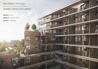
YEO STREET PH PLUS VERIFIED VIEWS DOCUMENT Appendix A Views Appendix B Cumulative Schemes Appendix C Methodology 1 PROJECT TITLE DATE
VIEW NUMBER LOCATION RENDER WIRELINE 1 GLAUCUS STREET R 2 JUNCTION OF YEO STREET WITH VIOLET ROAD R 3 LIMEHOUSE CUT TOWPATH UNDER THE BRIDGE ON MORRIS ROAD R 4 BALLADIER WALK R 5 LIMEHOUSE CUT TOWPATH WARNER TERRACE R 6 JUNCTION OF YEO STREET WITH WATTS GROVE R 7 LIMEHOUSE CUT TOWPATH UNDER BRIDGE ON UPPER NORTH STREET W 8 LIMEHOUSE CUT TOWPATH UNDER RAIL LINE BRIDGE W VIEWPOINT LOCATION MAP PROJECT TITLE DATE 2 3 PROJECT TITLE DATE
VIEW NUMBER LOCATION RENDER WIRELINE 1 GLAUCUS STREET R 2 JUNCTION OF YEO STREET WITH VIOLET ROAD R 3 LIMEHOUSE CUT TOWPATH UNDER THE BRIDGE ON MORRIS ROAD R 4 BALLADIER WALK R 5 LIMEHOUSE CUT TOWPATH WARNER TERRACE R 6 JUNCTION OF YEO STREET WITH WATTS GROVE R 7 LIMEHOUSE CUT TOWPATH UNDER BRIDGE ON UPPER NORTH STREET W 8 LIMEHOUSE CUT TOWPATH UNDER RAIL LINE BRIDGE W VIEWPOINT LOCATION MAP PROJECT TITLE DATE 2 3 PROJECT TITLE DATE
VIEWPOINT 01 CAMERA METADATA EXISTING CONDITION PROPOSED SCHEME DATE 19 08 2019 TIME 11 02 CAMERA CANON 5D MARK IV LENS I CANON TS E 24 MM F 3 5 L LOCATION GLAUCUS STREET HEIGHT TRIPOD AT 1 6M CUMULATIVE DEVELOPMENTS PROJECT TITLE DATE 4 5 PROJECT TITLE DATE
VIEWPOINT 01 CAMERA METADATA EXISTING CONDITION PROPOSED SCHEME DATE 19 08 2019 TIME 11 02 CAMERA CANON 5D MARK IV LENS I CANON TS E 24 MM F 3 5 L LOCATION GLAUCUS STREET HEIGHT TRIPOD AT 1 6M CUMULATIVE DEVELOPMENTS PROJECT TITLE DATE 4 5 PROJECT TITLE DATE
VIEWPOINT 02 CAMERA METADATA EXISTING CONDITION PROPOSED SCHEME DATE 19 08 2019 TIME 10 46 CAMERA CANON 5D MARK IV LENS I CANON TS E 24 MM F 3 5 L LOCATION JUNCTION OF YEO STREET VIOLET ROAD HEIGHT TRIPOD AT 1 6M CUMULATIVE DEVELOPMENTS PROJECT TITLE DATE 6 7 PROJECT TITLE DATE
VIEWPOINT 02 CAMERA METADATA EXISTING CONDITION PROPOSED SCHEME DATE 19 08 2019 TIME 10 46 CAMERA CANON 5D MARK IV LENS I CANON TS E 24 MM F 3 5 L LOCATION JUNCTION OF YEO STREET VIOLET ROAD HEIGHT TRIPOD AT 1 6M CUMULATIVE DEVELOPMENTS PROJECT TITLE DATE 6 7 PROJECT TITLE DATE
VIEWPOINT 03 CAMERA METADATA EXISTING CONDITION PROPOSED SCHEME EXISTING CONDITION PROPOSED SCHEME DATE 19 08 2019 TIME 11 55 CAMERA CANON 5D MARK IV LENS I CANON TS E 24 MM F 3 5 L LOCATION UNDER MORRIS ROAD BRIDGE HEIGHT TRIPOD AT 1 6M CUMULATIVE DEVELOPMENTS PROJECT TITLE DATE 8 9 PROJECT TITLE DATE
VIEWPOINT 03 CAMERA METADATA EXISTING CONDITION PROPOSED SCHEME EXISTING CONDITION PROPOSED SCHEME DATE 19 08 2019 TIME 11 55 CAMERA CANON 5D MARK IV LENS I CANON TS E 24 MM F 3 5 L LOCATION UNDER MORRIS ROAD BRIDGE HEIGHT TRIPOD AT 1 6M CUMULATIVE DEVELOPMENTS PROJECT TITLE DATE 8 9 PROJECT TITLE DATE
VIEWPOINT 04 CAMERA METADATA EXISTING CONDITION PROPOSED SCHEME EXISTING CONDITION PROPOSED SCHEME DATE 19 08 2019 TIME 09 45 CAMERA CANON 5D MARK IV LENS I CANON TS E 24 MM F 3 5 L LOCATION BALLADIER WALK HEIGHT TRIPOD AT 1 6M CUMULATIVE DEVELOPMENTS PROJECT TITLE DATE 10 11 PROJECT TITLE DATE
VIEWPOINT 04 CAMERA METADATA EXISTING CONDITION PROPOSED SCHEME EXISTING CONDITION PROPOSED SCHEME DATE 19 08 2019 TIME 09 45 CAMERA CANON 5D MARK IV LENS I CANON TS E 24 MM F 3 5 L LOCATION BALLADIER WALK HEIGHT TRIPOD AT 1 6M CUMULATIVE DEVELOPMENTS PROJECT TITLE DATE 10 11 PROJECT TITLE DATE
VIEWPOINT 05 CAMERA METADATA EXISTING CONDITION PROPOSED SCHEME EXISTING CONDITION PROPOSED SCHEME DATE 18 08 2019 TIME 17 25 CAMERA CANON 5D MARK IV LENS I CANON TS E 24 MM F 3 5 L LOCATION LIMEHOUSE CUT TOWPATH HEIGHT TRIPOD AT 1 6M CUMULATIVE DEVELOPMENTS PROJECT TITLE DATE 12 13 PROJECT TITLE DATE
VIEWPOINT 05 CAMERA METADATA EXISTING CONDITION PROPOSED SCHEME EXISTING CONDITION PROPOSED SCHEME DATE 18 08 2019 TIME 17 25 CAMERA CANON 5D MARK IV LENS I CANON TS E 24 MM F 3 5 L LOCATION LIMEHOUSE CUT TOWPATH HEIGHT TRIPOD AT 1 6M CUMULATIVE DEVELOPMENTS PROJECT TITLE DATE 12 13 PROJECT TITLE DATE
VIEWPOINT 06 CAMERA METADATA EXISTING CONDITION PROPOSED SCHEME EXISTING CONDITION PROPOSED SCHEME DATE 18 08 2019 TIME 17 13 CAMERA CANON 5D MARK IV LENS I CANON TS E 24 MM F 3 5 L LOCATION JUNCTION OF YEO STREET WATTS GROVE HEIGHT TRIPOD AT 1 6M CUMULATIVE DEVELOPMENTS PROJECT TITLE DATE 14 15 PROJECT TITLE DATE
VIEWPOINT 06 CAMERA METADATA EXISTING CONDITION PROPOSED SCHEME EXISTING CONDITION PROPOSED SCHEME DATE 18 08 2019 TIME 17 13 CAMERA CANON 5D MARK IV LENS I CANON TS E 24 MM F 3 5 L LOCATION JUNCTION OF YEO STREET WATTS GROVE HEIGHT TRIPOD AT 1 6M CUMULATIVE DEVELOPMENTS PROJECT TITLE DATE 14 15 PROJECT TITLE DATE
VIEWPOINT 07 CAMERA METADATA EXISTING CONDITION PROPOSED SCHEME EXISTING CONDITION PROPOSED SCHEME DATE 18 08 2019 TIME 15 48 CAMERA CANON 5D MARK IV LENS I CANON TS E 24 MM F 3 5 L LOCATION UNDER UPPER NORTH STREET BRIDGE HEIGHT TRIPOD AT 1 6M CUMULATIVE DEVELOPMENTS PROJECT TITLE DATE 16 17 PROJECT TITLE DATE
VIEWPOINT 07 CAMERA METADATA EXISTING CONDITION PROPOSED SCHEME EXISTING CONDITION PROPOSED SCHEME DATE 18 08 2019 TIME 15 48 CAMERA CANON 5D MARK IV LENS I CANON TS E 24 MM F 3 5 L LOCATION UNDER UPPER NORTH STREET BRIDGE HEIGHT TRIPOD AT 1 6M CUMULATIVE DEVELOPMENTS PROJECT TITLE DATE 16 17 PROJECT TITLE DATE
VIEWPOINT 08 CAMERA METADATA EXISTING CONDITION PROPOSED SCHEME EXISTING CONDITION PROPOSED SCHEME DATE 19 08 2019 TIME 10 04 CAMERA CANON 5D MARK IV LENS I CANON TS E 24 MM F 3 5 L LOCATION UNDER RAIL LINE BRIDGE HEIGHT TRIPOD AT 1 6M CUMULATIVE DEVELOPMENTS PROJECT TITLE DATE 18 19 PROJECT TITLE DATE
VIEWPOINT 08 CAMERA METADATA EXISTING CONDITION PROPOSED SCHEME EXISTING CONDITION PROPOSED SCHEME DATE 19 08 2019 TIME 10 04 CAMERA CANON 5D MARK IV LENS I CANON TS E 24 MM F 3 5 L LOCATION UNDER RAIL LINE BRIDGE HEIGHT TRIPOD AT 1 6M CUMULATIVE DEVELOPMENTS PROJECT TITLE DATE 18 19 PROJECT TITLE DATE
APPENDIX B CUMULATIVE SCHEMES PROJECT TITLE DATE 20 21 PROJECT TITLE DATE
APPENDIX B CUMULATIVE SCHEMES PROJECT TITLE DATE 20 21 PROJECT TITLE DATE
SCHEME ARCHITECT PLANNING NUMBER SOURCE LOCATION YEO STREET PH PLUS PHPLUS 5 YEO STREET WATTS GROVE WAUGH THISTLETON ARCHITECTS PA 17 00732 A1 MASSING CREATED USING PLANNING DRAWINGS LAND BOUNDED BY WATTS GROVE AND GALE STREET KEY CUMULATIVE DEVELOPMENT MAP PROJECT TITLE DATE 22 23 PROJECT TITLE DATE
SCHEME ARCHITECT PLANNING NUMBER SOURCE LOCATION YEO STREET PH PLUS PHPLUS 5 YEO STREET WATTS GROVE WAUGH THISTLETON ARCHITECTS PA 17 00732 A1 MASSING CREATED USING PLANNING DRAWINGS LAND BOUNDED BY WATTS GROVE AND GALE STREET KEY CUMULATIVE DEVELOPMENT MAP PROJECT TITLE DATE 22 23 PROJECT TITLE DATE
APPENDIX C BLACKPOINT DESIGN METHODOLOGY STATEMENT PROJECT TITLE DATE 24 25 PROJECT TITLE DATE
APPENDIX C BLACKPOINT DESIGN METHODOLOGY STATEMENT PROJECT TITLE DATE 24 25 PROJECT TITLE DATE
Project Methodology Photography Blackpoint Design were commissioned on behalf of City and Suburban Homes to produce a number of verified views of their proposal at 5 Yeo Street London The positions were identified and confirmed by CMAPlanning Each viewpoint is set up using a tripod set to a height of 1 6m to replicate average eye level height The centre point of the camera lens will be set up directly above a survey point using a plumb line to accurately position the centre point of the camera The camera used is top of the range a Canon D5 Mark IV which inherently embeds the correct date and time into the file Surveying All viewpoints will be shot using a Fixed Tilt Shift 17mm or 24mm lens unless otherwise requested by the client which have reduced distortion and therefore more accuracy due to the fixed focal length The tilt shift lenses also allow the digital capture chip to be shifted in respect to the centre of the camera lens to increase the height of the shot whilst keeping the horizon line central to the image This therefore prevents any 3 point perspective from being introduced and keeps the vertical lines parrallel within the scene A GPS Station is set up from a nearby parked location and a two person team carries out the survey on foot from this location The Leica Total station is typically set up over the marked camera positions If this is not possible the Camera Position will be surveyed remotely by laser or with a prism Each photograph is then checked and the shifted image is then blended together with the unshifted image to create a seamless photograph with extended height This photograph is then taken into 3DS Max a long with the survey points and camera information A virtual replica of each camera is then created at the exact OS location identified in the survey data and the verification process takes place to ensure that the survey points correctly line up with the matching points on the overlayed photography As all the survey points virtual camera and 3D model all relate to the same co ordinate system once the points all line up the corresponding photograph the virtual camera has then been fully verified and is locked to prevent any movement At least two of the control stations will be occupied by the GPS Antenna to establish a baseline and if possible several camera positions will be linked together forming a survey network 10 15 points per image will be chosen and these will be an even spread across the image near far left right bottom to top It is sometimes necessary to supplement points using survey poles with the photographer in attendance in positions where not enough stable points can be established Accurate Visual Representation Production Process Reflectorless laser measurements to features identified on the supplied images JPGs are constrained by distance approx 300 400m surface type and to some extent by the weather The 3D computer model was precisely aligned to a site plan on the OS coordinate grid system using the supplied floor plans and survey data supplied by the client The required horizon line within the image is established using the horizontal collimation of the theodolite set to 1 60m above the ground to identify 3 or 4 features that fall along the horizon line Within the software a virtual replica of each camera is then created at the exact OS location identified in the survey data and the verification process takes place to ensure that the survey points correctly line up with the matching points on the overlayed photography As all the survey points virtual camera and 3D model all relate to the same co ordinate system once the points all line up the corresponding photograph the virtual camera has then been fully verified and is locked to prevent any movement Surveying equipment used Leica Total Station Using the camera metadata the lighting is then matched to the photography using accurate latitude longitude and time data Materials are then applied to the virtual model matching those provided by the client and shown in the D A statement GPS Antenna A DWG fiile with camera locations and control points is then supplied together with a spreadsheet of co ordinates of camera locations and control points for the images Further to this a PDF of each view is supplied with the control points marked as a red cross and point number Ordnance Survey National Grid coordinates in metres will be used which correlate with the design coordinate scheme A computer generated render of the proposed building is then produced for each viewpoint using the verified camera lighting and photo realistic materials When compositing the images in Photoshop a degree of artistic licence is required to correctly integrate the proposal into the photography and make this appear as seamless and convincing as possible This process is more subjective and is achieved through a collaboration between illustrator client and architect The final computer generated verified image is then saved at high resolution and presented alongside the various techinal meta data and viewpoint location Location Marker PROJECT TITLE Point Co oridnate Spreadsheet DATE Points Overlayed Onto Base Photo 26 27 PROJECT TITLE DATE
Project Methodology Photography Blackpoint Design were commissioned on behalf of City and Suburban Homes to produce a number of verified views of their proposal at 5 Yeo Street London The positions were identified and confirmed by CMAPlanning Each viewpoint is set up using a tripod set to a height of 1 6m to replicate average eye level height The centre point of the camera lens will be set up directly above a survey point using a plumb line to accurately position the centre point of the camera The camera used is top of the range a Canon D5 Mark IV which inherently embeds the correct date and time into the file Surveying All viewpoints will be shot using a Fixed Tilt Shift 17mm or 24mm lens unless otherwise requested by the client which have reduced distortion and therefore more accuracy due to the fixed focal length The tilt shift lenses also allow the digital capture chip to be shifted in respect to the centre of the camera lens to increase the height of the shot whilst keeping the horizon line central to the image This therefore prevents any 3 point perspective from being introduced and keeps the vertical lines parrallel within the scene A GPS Station is set up from a nearby parked location and a two person team carries out the survey on foot from this location The Leica Total station is typically set up over the marked camera positions If this is not possible the Camera Position will be surveyed remotely by laser or with a prism Each photograph is then checked and the shifted image is then blended together with the unshifted image to create a seamless photograph with extended height This photograph is then taken into 3DS Max a long with the survey points and camera information A virtual replica of each camera is then created at the exact OS location identified in the survey data and the verification process takes place to ensure that the survey points correctly line up with the matching points on the overlayed photography As all the survey points virtual camera and 3D model all relate to the same co ordinate system once the points all line up the corresponding photograph the virtual camera has then been fully verified and is locked to prevent any movement At least two of the control stations will be occupied by the GPS Antenna to establish a baseline and if possible several camera positions will be linked together forming a survey network 10 15 points per image will be chosen and these will be an even spread across the image near far left right bottom to top It is sometimes necessary to supplement points using survey poles with the photographer in attendance in positions where not enough stable points can be established Accurate Visual Representation Production Process Reflectorless laser measurements to features identified on the supplied images JPGs are constrained by distance approx 300 400m surface type and to some extent by the weather The 3D computer model was precisely aligned to a site plan on the OS coordinate grid system using the supplied floor plans and survey data supplied by the client The required horizon line within the image is established using the horizontal collimation of the theodolite set to 1 60m above the ground to identify 3 or 4 features that fall along the horizon line Within the software a virtual replica of each camera is then created at the exact OS location identified in the survey data and the verification process takes place to ensure that the survey points correctly line up with the matching points on the overlayed photography As all the survey points virtual camera and 3D model all relate to the same co ordinate system once the points all line up the corresponding photograph the virtual camera has then been fully verified and is locked to prevent any movement Surveying equipment used Leica Total Station Using the camera metadata the lighting is then matched to the photography using accurate latitude longitude and time data Materials are then applied to the virtual model matching those provided by the client and shown in the D A statement GPS Antenna A DWG fiile with camera locations and control points is then supplied together with a spreadsheet of co ordinates of camera locations and control points for the images Further to this a PDF of each view is supplied with the control points marked as a red cross and point number Ordnance Survey National Grid coordinates in metres will be used which correlate with the design coordinate scheme A computer generated render of the proposed building is then produced for each viewpoint using the verified camera lighting and photo realistic materials When compositing the images in Photoshop a degree of artistic licence is required to correctly integrate the proposal into the photography and make this appear as seamless and convincing as possible This process is more subjective and is achieved through a collaboration between illustrator client and architect The final computer generated verified image is then saved at high resolution and presented alongside the various techinal meta data and viewpoint location Location Marker PROJECT TITLE Point Co oridnate Spreadsheet DATE Points Overlayed Onto Base Photo 26 27 PROJECT TITLE DATE
DESCRIPTION SOURCE ARCHITECTURAL 3D MODEL SUPPLIED BY ARCHITECT ON CORRECT OS DATA CO ORDINATES WITH CORRECT AOD HEIGHTS SURVEY DATA SUPPLIED BY __________________________ CONSENTED SCHEMES MODELLED BY BLACKPOINT DESIGN BASED ON AVAILABLE PLANNING PRE APP DOCUMENTS VIEWPOINT LOCATIONS SUPPLIED BY ______________________ AGREED IN COLLABORATION WITH PLANNING OFFICER HERITAGE CONSULTANTS AND ARCHITECTS PHOTOGRAPHY BASE PHOTOGRAPHY SUPPLIED BY BLACKPOINT DESIGN Z MAP DATA SUPPLIED BY ARCHITECT SOURCED THROUGH ZMAPPING COM TOPOGRAPHIC SURVEY SUPPLIED BY ARCHITECT ON CORRECT OS DATA CO ORDINATES PROJECT TITLE DATE 28 29 PROJECT TITLE DATE
DESCRIPTION SOURCE ARCHITECTURAL 3D MODEL SUPPLIED BY ARCHITECT ON CORRECT OS DATA CO ORDINATES WITH CORRECT AOD HEIGHTS SURVEY DATA SUPPLIED BY __________________________ CONSENTED SCHEMES MODELLED BY BLACKPOINT DESIGN BASED ON AVAILABLE PLANNING PRE APP DOCUMENTS VIEWPOINT LOCATIONS SUPPLIED BY ______________________ AGREED IN COLLABORATION WITH PLANNING OFFICER HERITAGE CONSULTANTS AND ARCHITECTS PHOTOGRAPHY BASE PHOTOGRAPHY SUPPLIED BY BLACKPOINT DESIGN Z MAP DATA SUPPLIED BY ARCHITECT SOURCED THROUGH ZMAPPING COM TOPOGRAPHIC SURVEY SUPPLIED BY ARCHITECT ON CORRECT OS DATA CO ORDINATES PROJECT TITLE DATE 28 29 PROJECT TITLE DATE